Have you ever come across process valve symbols in engineering diagrams and felt confused about what they mean?
In engineering, process valve symbols are used to represent different types of valves and their functions in diagrams, such as piping and instrumentation diagrams (P&IDs).
This article aims to demystify process valve symbols by providing a clear and concise explanation of commonly used symbols. By the end of this article, you will have a solid understanding of process valve symbols, enabling you to interpret engineering diagrams with ease.
What is a Piping and Instrumentation Diagram (P&ID)?
A piping and instrumentation diagram (P&ID) is a type of technical drawing that illustrates the physical layout of piping systems and the instrumentation used in a process. It is commonly used in the fields of engineering and process control to document and communicate the design and operation of a system. In a P&ID, various symbols are used to represent different components, such as valves, pumps, heat exchangers, and instruments. These symbols are connected by lines to show how the components are interconnected and how fluids or gases flow through the system. P&IDs are essential in the construction, operation, and maintenance of industrial plants and processes.
P&IDs provide a visual representation of a system’s components and their interactions, allowing engineers and operators to understand how the system works and how it can be optimised. By following a P&ID, technicians can identify and locate specific equipment, valves, and instruments within a system. This is crucial for troubleshooting, maintenance, and repairs. Additionally, P&IDs can be used to design new systems or modify existing ones, ensuring accurate and efficient operations.
The information depicted in a P&ID includes not only the physical layout of the system but also the process parameters, such as pressure, temperature, flow rate, and level. These parameters are often measured and controlled using instruments, and the P&ID shows their locations and connections to the process piping. This allows operators to monitor and adjust the system to maintain optimal performance and safety.
P&IDs are typically created by engineers and drafters using specialised computer-aided design (CAD) software. The software provides a library of symbols and tools to easily create and modify P&IDs. Once completed, P&IDs are often printed or displayed electronically for reference by operators, maintenance personnel, and other stakeholders. They are also often updated throughout the lifecycle of a system to reflect any changes or modifications made.
What are the Common Process Valve Symbols?
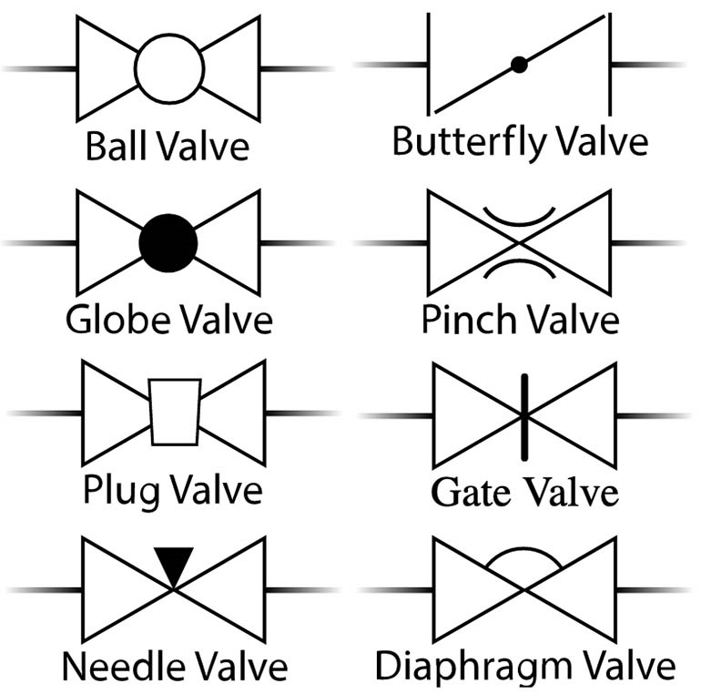
The universal symbol for a 2 way valve is two triangles pointing to each other with the inner points touching. The type of valve can be determined by the shape that is added to the centre where the inner points touch.
Some of the most common process valves used in P&IDs include the following.
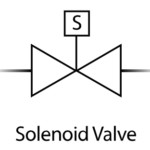
The solenoid valve symbol has the same two triangles pointing to each other but instead of having a shape in the middle there is a S in a box above to indicate this 2 way valve is operated by a solenoid.
Actuators
Actuator symbols are similar to the solenoid valve symbol in that the differentiation of the actuator is above the valve diagram. As seen in the below examples this is a 2 way ball valve but with a different actuator for each. Some of the actuators available include manual operation, pneumatic actuator, diaphragm and piston type, electric actuator and hydraulic actuators.
Some of the other common symbols that you need to know include the following.
Process Lines
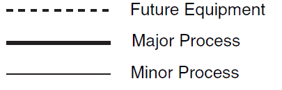
The process line symbols can be seen on the right, depending on the process depends on the thickness of the line. If the equipment is not yet in the system this is shown as a future process line and is dotted rather than solid.
Signal Lines
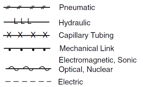
The signal lines symbols can also be seen on the right, depending on what the signal is depends on how the line looks.
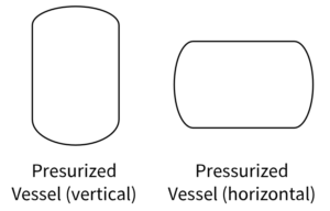
The vessel symbol is an oval shape similar to how an air receiver looks and is either horizontal or vertical depending on the orientation of the vessel.
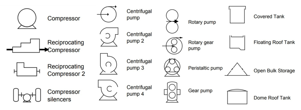
Equipment
There are many different symbols for equipment. Some of the more common equipment such as compressors, centrifugal pumps, rotary gear pumps and tanks can be seen on the right.
In conclusion, understanding the process valve symbols used within a P&ID is crucial for anyone working in the field of engineering or process control. These symbols serve as a universal language, allowing professionals to effectively communicate and troubleshoot complex systems. So, whether you’re a seasoned engineer or just starting out, mastering these symbols will open doors to endless possibilities in your career.