
What is a Piping and Instrumentation Diagram? (P&ID)
A P&ID, or Piping and Instrumentation Diagram, is the cornerstone of the process industry, a schematic illustration that details the piping and related components of a physical process flow. These diagrams are pivotal in the design, operation, and maintenance of process systems, serving as a primary reference point for engineers and operators. The symbols represented in a P&ID are a universal language, designed to be understood by all stakeholders involved in a project. Understanding these symbols is essential for anyone involved in the engineering, maintenance, and operation of a plant.
Process Valves, with over 35 years of experience, recognises the importance of P&IDs in ensuring that the valves and actuated valve systems we provide seamlessly integrate into complex process systems. In the next section, we will explore the varied uses of P&IDs and how they become an essential part of system management and documentation.
What are the uses of P&IDs?
P&IDs are multifaceted tools used across various stages of a process system’s lifecycle. Initially, they are utilised during the design phase, allowing engineers to layout the system’s architecture accurately. As the project moves to construction, P&IDs guide the assembly of components, ensuring that each valve, pipe, and instrument is placed according to the specified design. These diagrams are also indispensable during the operational phase, where they assist in training personnel, guiding troubleshooting procedures, and aiding in process optimisation.
For Process Valves, P&IDs serve as a critical reference to ensure the valves we supply are suitable for the specific applications of our clients. This tailored approach helps in preventing costly downtime and extends the longevity of the system’s operation. Moving forward, the next section will delve into the array of symbols used in P&IDs, their meanings, and their significance in ensuring the correct application of our product range in your systems.
Symbols Used in P&IDs
The complexity of P&IDs is distilled into a comprehensive set of symbols, each designed to convey detailed information about the components they represent. These symbols are not mere representations; they are the language through which the functionality, interconnections, and control measures of process systems are communicated. From simple pipes to intricate control loops, every line and symbol on a P&ID has a specific meaning, and understanding these symbols is crucial for anyone who interacts with the process flow.
At Process Valves, our expertise extends to interpreting these symbols, ensuring that the valves we provide are not only technically sound but also appropriate for the indicated application. Whether it’s isolating sections of a system, regulating flow, or preventing backflow, the right valve for each symbol is paramount. Next, we will delve into valve symbols specifically, illustrating how various types of valves are represented and the importance of these symbols in selecting the correct valve for your needs.
Valve Symbols for P&IDs
Valve symbols are a critical subset of the symbols used in P&IDs, indicating the type and function of the valve within the process system. These symbols can range from simple ball valves to more complex control valves that include various enhancements to depict their specific characteristics and operations. The symbol provides a snapshot of the valve’s function—whether it modulates flow, acts as a non-return element, or isolates sections of the system.
The universal symbol for a 2 way valve is two triangles pointing towards each other with the tips touching, as can be seen on the image on the right.
As you can see from the image if it’s a 3 way or 4 way valve then another triangle is added with all the points touching in the middle.
To determine what the valve actually is e.g. ball valve or butterfly valve a shape is added to the centre where the triangle points touch to allow identification.

At Process Valves, our understanding of these symbols is integral to offering clients the right valve for their system. Our catalogue of products is informed by the nuances of these symbols, ensuring that each valve delivered not only meets the specifications but also performs as intended within the system’s broader context. Up next, we’ll break down these symbols further, starting with the types of valves represented in P&IDs, followed by the types of actuators and fail-safe options, detailing how each plays a role in the safe and efficient operation of your process system.
Type of Valves
The type of valve symbol in a P&ID is indicative of its specific function and operation within the process system. These symbols are standardised to represent various valve types such as ball, gate, globe, check, and butterfly valves, each with its unique shape and design on the diagram.
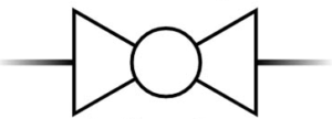
Ball Valve Symbol
The ball valve symbol is represented by a plain circle drawn straight over the centre where the two triangles meet.
From the above section showing the different valve symbols we can see the image on the right is a 2 way ball valve.
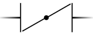
Butterfly Valve Symbol
The butterfly valve symbol is represented by a line drawn diagonally from the bottom left of the first triangle to the top right of the second triangle with a smaller filled circle in the middle.
From the above section showing the different valve symbols we can see the image on the right is a 2 way butterfly valve.
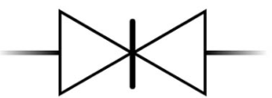
Gate Valve Symbol
The gate valve symbol is represented by a thick line drawn straight through the middle of the centre where the two triangles meet.
From the above section showing the different valve symbols we can see the image on the right is a 2 way gate valve.
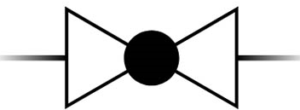
Globe Valve Symbol
The globe valve symbol is represented by a filled circle drawn straight over the centre where the two triangles meet. This looks exactly the same as the ball valve other than the circle on a globe valve is filled whereas the ball valve is plain.
From the above section showing the different valve symbols we can see the image on the right is a 2 way globe valve.
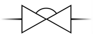
Diaphragm Valve Symbol
The diaphragm valve symbol is represented by a plain semi circle drawn above the centre where the two triangles meet.
From the above section showing the different valve symbols we can see the image on the right is a 2 way diaphragm valve.
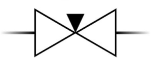
Needle Valve Symbol
The needle valve symbol is represented by a small filled triangle pointing down with the tip meeting in the centre with the other triangles. This looks similar to a 3 way valve shown in the above section but can be easily differentiated due to the triangle being significantly smaller and filled to avoid any confusion.
From the above section showing the different valve symbols we can see the image on the right is a 2 way needle valve.
Pinch Valve Symbol
The pinch valve symbol is represented by 2 small curved lines that flow with the space above and below where the triangles meet in the centre.
From the above section showing the different valve symbols we can see the image on the right is a 2 way pinch valve.

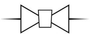
Plug Valve Symbol
The plug valve symbol is represented by a rectangle that goes through where the triangles meet in the centre and tapers near the bottom like a cork representing the plug.
From the above section showing the different valve symbols we can see the image on the right is a 2 way plug valve.
Process Valves offers a broad spectrum of valve types, each chosen to meet the precise demands of different systems as indicated by the above P&ID symbols. Our expertise lies in matching the correct valve type to its symbolic representation on the P&ID, ensuring compatibility and functionality within the client’s system. Following this section, we will discuss the types of actuators that accompany these valves and the symbols that represent them in P&IDs, emphasising the role they play in automation and control within process systems.
Type of Actuators
Actuators in a P&ID are represented by symbols that indicate the mechanism through which a valve is operated. These symbols differentiate between manual mechanisms, such as handwheels or levers, and automated actuators like pneumatic, hydraulic, or electric. The actuator symbol is positioned above the valve type symbol and shows how the valve is actuated. A crucial detail for the correct operation and integration into the system’s control strategy.
All of the below show a 2 way ball valve as we know from the above sections, each with a different actuation option.
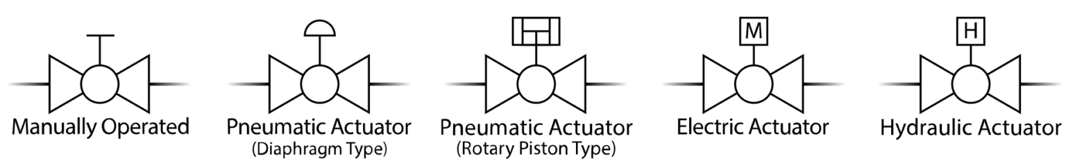
Process Valves’ selection includes an array of actuators to complement our valve offerings, ensuring that we can provide a complete solution that aligns with the operational symbols on your P&ID. From manually operated valves for simple on-off control to sophisticated automated valves critical for precision process control, our range caters to the varied symbols you will encounter. Next, we will consider the fail-safe options available for actuators, which are essential for maintaining safety and preventing accidents in the event of a power or control loss, and how these are represented within the P&ID symbols.
Fail Safe Options
Fail-safe options for valves and actuators are a vital consideration in process safety, ensuring that systems revert to a safe state during an unexpected event or failure. In P&IDs, these options are symbolized distinctly to convey what action a valve will take—either closing, opening, or maintaining its last position when control is lost. These symbols are crucial for engineers and operators to understand and implement the correct fail-safe measures.
Fail Closed Valve Symbol
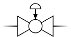
The fail safe closed option is represented on a valve symbol drawing in the form of an arrow pointing down towards the centre of the valve type drawing.
From the sections we have already covered we can see the image on the right represents a 2 way ball valve with a pneumatic diaphragm type actuator with a fail safe closed mechanism
Fail Open Valve Symbol
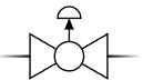
The fail safe open option is represented on a valve symbol drawing in the form of an arrow pointing up towards the centre of the actuator controlling the valve type.
From the sections we have already covered we can see the image on the right represents a 2 way ball valve with a pneumatic diaphragm type actuator with a fail safe open mechanism
At Process Valves, we understand the importance of these fail-safe symbols in P&IDs and offer valves and actuators that conform to these safety requirements. Our product range includes valves with built-in fail-safe mechanisms such as spring-return actuators or battery-backup systems, designed to respond appropriately to the fail-safe symbols on your P&ID, ensuring the safety and integrity of your process systems.
In the following section, we will explore the various end connections that valves can have, which are also represented in P&IDs. These connections are critical for ensuring the correct integration of the valve into the piping system, with symbols representing flanged, threaded, or welded connections among others.
End Connections
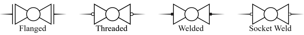
End connections on valves are crucial for their integration into the piping system, dictating how they will be connected to the existing pipeline. In P&IDs, these connections are depicted through a set of standardized symbols that indicate whether a valve is flanged, threaded, welded, or socket welded. The symbols are shown on each side of the triangles in the centre where the process lines come out and are represented as simple shapes.
As you can see from the below image each of the valves is a 2 way ball valve but with a different end connection. Flanged ends are represented by straight lines, threaded features plain circles, welded consists of filled squares and socket weld is plain squares. These simple shapes denote important details about how the valve interfaces with the physical system, which can impact the installation process and maintenance protocols.
At Process Valves, we supply valves with a variety of end connections, understanding that the choice of connection is as critical as the valve selection itself. Our range ensures that whatever the symbolic representation on the P&ID, we can provide a valve with the corresponding end connection, facilitating a smooth installation and optimal system integration.
The next section will address the symbols associated with process lines, including pipes, tubes, and hoses, which are integral components of any P&ID and play a significant role in the physical layout and flow dynamics of a process system.
Process Lines (Pipes, Tubes & Hoses)
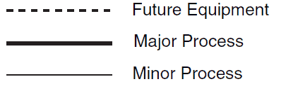
Process lines, comprising pipes, tubes, and hoses, are the circulatory system of any process flow diagram, depicted in P&IDs with a variety of symbols. Each line type is represented by a unique symbol, distinguishing between the different materials and sizes.
The image on the right shows the differences between major and minor processes as well as any future planning of equipment.
The diameter and material specifications are often noted alongside these symbols to provide further detail on the line’s characteristics.
Process Valves appreciates the significance of these process line symbols in P&IDs. Our comprehensive understanding enables us to advise on the appropriate valve selection, considering the type of process line it will be connected to. This ensures seamless compatibility and efficiency, whether the system requires robust pipes for high-pressure applications or flexible hoses for dynamic processing environments.
Up next, we will discuss the variety of pipe symbols that are found in P&IDs, elaborating on their meanings and implications for the process system, ensuring that each component is matched perfectly to its intended function.
Various Pipe Symbols
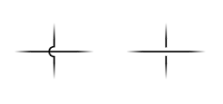
In P&IDs, various pipe symbols are employed to convey a wealth of information about the pipes within a system, such as flow direction, permanent and temporary connections, and the presence of slopes or fittings. These symbols allow for a detailed understanding of the physical layout of the piping system, including branches, reducers, expansions, and other features that are critical to the system’s function and maintenance.
The image on the right is a representation of this. The left cross section shows a process line going under another and the cross section on the right shows the process line going over it. This is actually not a physical representation of the pipes they may never cross it’s just used as a representation to illustrate two pipes on a drawing that are not connected.
At Process Valves, the precise interpretation of these pipe symbols is an essential part of our service, ensuring that the valves we supply are perfectly suited to the designated pipe function and configuration. Whether the application requires a straightforward gate valve for a straight-run pipe or a more complex solution for a system with multiple branches and reducers, our technical expertise and extensive product range are geared towards providing the right valve for the right place, as indicated by the pipe symbols on your P&ID.
We will now move on to discuss various signal symbols in P&IDs. These symbols are integral to understanding the communication and control aspects of process systems, indicating how signals are sent and received within the system, which is pivotal for the operation and monitoring of the valves we provide.
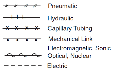
Various Signal Symbols
Signal symbols in P&IDs play a pivotal role in illustrating the control and communication lines that govern the operation of process systems. These symbols denote the types of signals — whether they are pneumatic, hydraulic, electric or a number of other options, each represented on the image on the right — that activate and regulate valves and other equipment. They provide insights into the control logic and how different components of the system interact and respond to each other, which is critical for automation and safety systems.
Understanding these signal symbols is essential for Process Valves when advising on the correct valve automation and control requirements. Our expertise ensures that the actuated valve systems we supply are compatible with the signal types used in our customers’ processes, enhancing the precision and reliability of their operations.
Following this section, we will explore other equipment commonly depicted in P&IDs, such as vessels, and the various types of pumps, fans, and compressors. This will include how these components are represented and their relationship to the valves and actuated systems we specialise in.
Common Major Process Component P&ID Symbols
Vessels
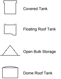
Vessels are a key component in many industrial processes and are represented in P&IDs by a set of symbols that detail their type and function.
The images on the right represent vertical vessels and horizontal vessels as well as a range of different specific vessels such as a covered tank, floating roof tank, open bulk storage and dome roof tanks.
These symbols help identify the vessels’ roles within the process, whether they are for mixing, separation, reaction, or storage. The design and interpretation of these symbols take into account factors such as pressure ratings, temperature conditions, and material compatibility, which are crucial for the safe and efficient operation of the process.

Process Valves’ expertise encompasses not only the valves but also the pressure vessels and how they integrate with these vessels. The correct valve selection and placement are essential to ensure that the vessel operates safely, under the right conditions, and with the desired outcome. Whether the vessel requires precise pressure control, flow regulation, or emergency relief, we offer valves that meet the rigorous demands of these applications as denoted by the vessel symbols on a P&ID.
Next, we will look at the symbols representing pumps, fans, and compressors in P&IDs. Understanding these symbols is important as they often work in conjunction with valves to move, compress, or ventilate gases or liquids within a process system.
Pumps & Compressors
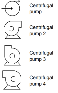
Pumps and compressors are dynamic components within process systems, and their operation is critical for moving, elevating pressure, and circulating fluids and gases.
In P&IDs, these pieces of equipment are represented by distinct symbols that provide information on their type and operational characteristics.
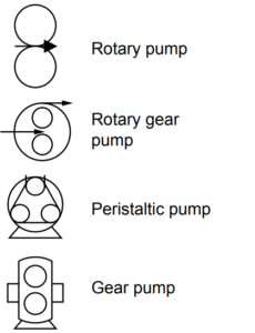
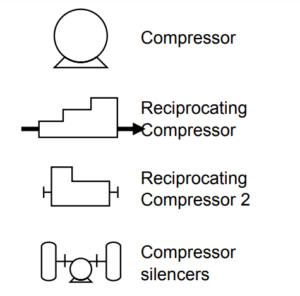
Pump symbols may vary to indicate different types such as centrifugal, rotary pump, rotary gear pump, peristaltic pump or gear pumps while compressors have their own set of symbols to differentiate between axial, centrifugal, or reciprocating types.
For Process Valves, a deep understanding of these symbols is necessary as the selection of valves often depends on the characteristics of these devices. Valves must be compatible with the pressures and flows generated by pumps, work efficiently under the conditions created by compressors, and ensure proper functioning within ventilation systems involving fans. Our range includes valves specifically designed to operate effectively with these systems, providing reliability and control as required by the P&ID specifications.
In the next section, we will provide more detailed information and a complete guide to understanding P&IDs, offering insights into how each symbol and component interconnects to form a cohesive and functional process system. This guide will be invaluable for anyone looking to gain a comprehensive view of P&IDs and their practical applications in the field.
More Information – Complete PDF Guide
For those seeking a deeper understanding of P&IDs and their practical applications, a complete pdf guide is available by clicking here.
This guide encompasses not just the basic symbols, but also the instruments, valves, pumps, vessels, filters, compressors, heat exchangers, dryers, general, mixers, crushers, centrifuges, motors, peripheral, piping and connecting shapes for a complete guide to designing or identifying P&ID symbols.
Process Valves positions itself as not just a supplier but a knowledge resource for clients who need to navigate the complexities of P&IDs. Our commitment extends beyond providing high-quality valves and actuators; we aim to support our clients in understanding how our products fit into their systems according to P&ID representations. This ensures that the solutions we offer are not only technically suitable but also practically relevant to our clients’ operational needs.
Piping and Instrumentation Diagrams are the blueprints that articulate the lifelines of process industries, embodying the detailed choreography of every component that makes up a process system. They are not merely diagrams but are foundational tools for the planning, execution, maintenance, and optimisation of complex industrial operations. The symbols within these diagrams serve as a precise language, allowing for clear communication among diverse engineering disciplines and operational teams.
Process Valves stands as a partner in this realm, offering not just a product but a promise — the promise of delivering valves and actuated systems that are in perfect harmony with the requirements laid out in P&IDs. With our deep technical knowledge and wide range of products, we empower our clients to translate the symbols on their diagrams into efficient, reliable, and safe process systems.
For further inquiries or to discuss your valve requirements in detail, then please contact us and we will ensure that you receive personalised and expert assistance for your specific needs.